| Product Name |
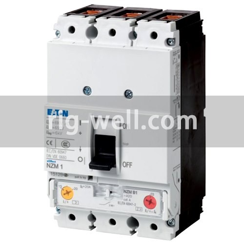
Eaton Moeller series NZM molded case circuit breaker thermo-magnetic
|
| Catalog Number |
281234
|
| Model Code |
NZMN1-A160
|
| EAN |
4015082812348
|
| Product Length/Depth |
88 mm
|
| Product Height |
145 mm
|
| Product Width |
90 mm
|
| Product Weight |
1.046 kg
|
| Used with |
Enclosure 100 x 800 x 600 mm
|
| Amperage Rating |
160 A
|
| Voltage rating |
690 V – 690 V
|
| Circuit breaker frame type |
NZM1
|
| Features |
Protection unit
|
| 10.10 Temperature rise |
The panel builder is responsible for the temperature rise calculation. Eaton will provide heat dissipation data for the devices.
|
| 10.11 Short-circuit rating |
Is the panel builder’s responsibility. The specifications for the switchgear must be observed.
|
| 10.12 Electromagnetic compatibility |
Is the panel builder’s responsibility. The specifications for the switchgear must be observed.
|
| 10.13 Mechanical function |
The device meets the requirements, provided the information in the instruction leaflet (IL) is observed.
|
| 10.2.2 Corrosion resistance |
Meets the product standard’s requirements.
|
| 10.2.3.1 Verification of thermal stability of enclosures |
Meets the product standard’s requirements.
|
| 10.2.3.2 Verification of resistance of insulating materials to normal heat |
Meets the product standard’s requirements.
|
| 10.2.3.3 Resist. of insul. mat. to abnormal heat/fire by internal elect. effects |
Meets the product standard’s requirements.
|
| 10.2.4 Resistance to ultra-violet (UV) radiation |
Meets the product standard’s requirements.
|
| 10.2.5 Lifting |
Does not apply, since the entire switchgear needs to be evaluated.
|
| 10.2.6 Mechanical impact |
Does not apply, since the entire switchgear needs to be evaluated.
|
| 10.2.7 Inscriptions |
Meets the product standard’s requirements.
|
| 10.3 Degree of protection of assemblies |
Does not apply, since the entire switchgear needs to be evaluated.
|
| 10.4 Clearances and creepage distances |
Meets the product standard’s requirements.
|
| 10.5 Protection against electric shock |
Does not apply, since the entire switchgear needs to be evaluated.
|
| 10.6 Incorporation of switching devices and components |
Does not apply, since the entire switchgear needs to be evaluated.
|
| 10.7 Internal electrical circuits and connections |
Is the panel builder’s responsibility.
|
| 10.8 Connections for external conductors |
Is the panel builder’s responsibility.
|
| 10.9.2 Power-frequency electric strength |
Is the panel builder’s responsibility.
|
| 10.9.3 Impulse withstand voltage |
Is the panel builder’s responsibility.
|
| 10.9.4 Testing of enclosures made of insulating material |
Is the panel builder’s responsibility.
|
| Pollution degree |
3
|
| Mounting Method |
DIN rail (top hat rail) mounting optional
Built-in device fixed built-in technique Fixed |
| Climatic proofing |
Damp heat, constant, to IEC 60068-2-78
Damp heat, cyclic, to IEC 60068-2-30 |
| Equipment heat dissipation, current-dependent |
36.1 W
|
| Utilization category |
A (IEC/EN 60947-2)
|
| Isolation |
500 V AC (between auxiliary contacts and main contacts)
300 V AC (between the auxiliary contacts) |
| Ambient operating temperature – max |
70 °C
|
| Ambient operating temperature – min |
-25 °C
|
| Ambient storage temperature – max |
70 °C
|
| Ambient storage temperature – min |
40 °C
|
| Number of auxiliary contacts (change-over contacts) |
0
|
| Number of auxiliary contacts (normally closed contacts) |
0
|
| Number of auxiliary contacts (normally open contacts) |
0
|
| Protection against direct contact |
Finger and back-of-hand proof to DIN EN 50274/VDE 0106 part 110
|
| Degree of protection |
IP20
IP20 (basic degree of protection, in the operating controls area) |
| Direction of incoming supply |
As required
|
| Electrical connection type of main circuit |
Frame clamp
|
| Lifespan, mechanical |
20000 operations
|
| Overvoltage category |
III
|
| Degree of protection (IP), front side |
IP66 (with door coupling rotary handle)
IP40 (with insulating surround) |
| Degree of protection (terminations) |
IP00 (terminations, phase isolator and strip terminal)
IP10 (tunnel terminal) |
| Number of poles |
Three-pole
|
| Terminal capacity (copper strip) |
Min. 2 segments of 9 mm x 0.8 mm at box terminal
Max. 9 segments of 9 mm x 0.8 mm at box terminal |
| Lifespan, electrical |
7500 operations at 400 V AC-1
5000 operations at 690 V AC-1 7500 operations at 415 V AC-1 |
| Functions |
System and cable protection
|
| Type |
Circuit breaker
|
| Special features |
|
| Application |
Use in unearthed supply systems at 690 V
|
| Shock resistance |
20 g (half-sinusoidal shock 20 ms)
|
| Position of connection for main current circuit |
Front side
|
| Rated operational current for specified heat dissipation (In) |
160 A
|
| Power loss |
36.1 W
|
| Release system |
Thermomagnetic release
|
| Short-circuit total breaktime |
< 10 ms
|
| Short-circuit release non-delayed setting – max |
1280 A
|
| Short-circuit release non-delayed setting – min |
1280 A
|
| Terminal capacity (control cable) |
0.75 mm² – 1.5 mm² (2x)
0.75 mm² – 2.5 mm² (1x) |
| Terminal capacity (copper busbar) |
M6 at rear-side screw connection
Max. 16 mm x 5 mm direct at switch rear-side connection Min. 12 mm x 5 mm direct at switch rear-side connection |
| Terminal capacity (copper solid conductor/cable) |
16 mm² (1x) at tunnel terminal
6 mm² – 16 mm² (2x) direct at switch rear-side connection 10 mm² – 16 mm² (1x) at box terminal 10 mm² – 16 mm² (1x) direct at switch rear-side connection 6 mm² – 16 mm² (2x) at box terminal |
| Terminal capacity (aluminum solid conductor/cable) |
10 mm² – 16 mm² (2x) direct at switch rear-side connection
10 mm² – 16 mm² (1x) direct at switch rear-side connection 16 mm² (1x) at tunnel terminal |
| Terminal capacity (copper stranded conductor/cable) |
10 mm² – 70 mm² (1x) direct at switch rear-side connection
25 mm² (2x) direct at switch rear-side connection 25 mm² – 95 mm² (1x) at 1-hole tunnel terminal 10 mm² – 70 mm² (1x) at box terminal 6 mm² – 25 mm² (2x) at box terminal |
| Terminal capacity (aluminum stranded conductor/cable) |
25 mm² – 35 mm² (2x) direct at switch rear-side connection
25 mm² – 35 mm² (1x) direct at switch rear-side connection 25 mm² – 95 mm² (1x) at tunnel terminal |
| Handle type |
Rocker lever
|
| Short delay current setting (Isd) – max |
0 A
|
| Short delay current setting (Isd) – min |
0 A
|
| Instantaneous current setting (Ii) – max |
1600 A
|
| Instantaneous current setting (Ii) – min |
960 A
|
| Number of operations per hour – max |
120
|
| Overload current setting (Ir) – max |
160 A
|
| Overload current setting (Ir) – min |
125 A
|
| Rated short-circuit breaking capacity Ics (IEC/EN 60947) at 230 V, 50/60 Hz |
85 kA
|
| Rated short-circuit breaking capacity Ics (IEC/EN 60947) at 400/415 V, 50/60 Hz |
50 kA
|
| Rated short-circuit breaking capacity Ics (IEC/EN 60947) at 440 V, 50/60 Hz |
35 kA
|
| Rated short-circuit breaking capacity Ics (IEC/EN 60947) at 525 V, 50/60 Hz |
10 kA
|
| Rated short-circuit breaking capacity Ics (IEC/EN 60947) at 690 V, 50/60 Hz |
7.5 kA
|
| Rated short-circuit making capacity Icm at 400/415 V, 50/60 Hz |
105 kA
|
| Rated short-circuit making capacity Icm at 440 V, 50/60 Hz |
74 kA
|
| Rated short-circuit making capacity Icm at 525 V, 50/60 Hz |
40 kA
|
| Rated short-circuit making capacity Icm at 690 V, 50/60 Hz |
17 kA
|
| Standard terminals |
Box terminal
|
| Optional terminals |
Connection on rear. Screw terminal. Tunnel terminal
|
| Rated short-circuit making capacity Icm at 240 V, 50/60 Hz |
187 kA
|
| Rated impulse withstand voltage (Uimp) at auxiliary contacts |
6000 V
|
| Rated impulse withstand voltage (Uimp) at main contacts |
6000 V
|
| Rated insulation voltage (Ui) |
690 V AC
|