Ordering data
| Product type description |
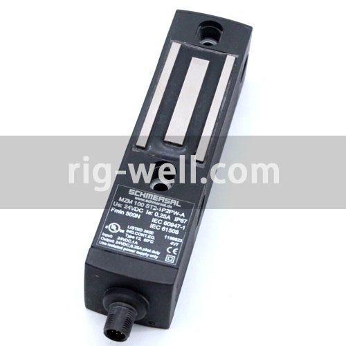
MZM 100 ST2-1P2PW-A |
| Article number (order number) |
101199623 |
| EAN (European Article Number) |
4030661388816 |
| eCl@ss number, version 12.0 |
27-27-26-03 |
| eCl@ss number, version 11.0 |
27-27-26-03 |
| eCl@ss number, version 9.0 |
27-27-26-03 |
| ETIM number, version 7.0 |
EC002593 |
| ETIM number, version 6.0 |
EC002593 |
Approvals – Standards
| Certificates |
TÜV cULus UKCA |
General data
| Standards |
EN ISO 13849-1 EN ISO 14119 EN IEC 60947-5-3 EN IEC 61508 |
| Coding |
Universal coding |
| Coding level according to EN ISO 14119 |
Low |
| Working principle |
inductive |
| Housing material |
Plastic, glass-fibre reinforced thermoplastic, self-extinguishing |
| Reaction time, maximum |
150 ms |
| Duration of risk, maximum |
150 ms |
| Gross weight |
618 g |
General data – Features
| Power to lock |
Yes |
| Solenoid interlock monitored |
Yes |
| Short circuit detection |
Yes |
| Cross-circuit detection |
Yes |
| Series-wiring |
Yes |
| Safety functions |
Yes |
| Integral system diagnostics, status |
Yes |
| Number of safety contacts |
2 |
| Safety classification |
| Vorschriften |
EN ISO 13849-1 EN IEC 61508 |
Safety classification – Interlocking function
| Performance Level, up to |
e |
| Category |
4 |
| PFH value |
3.54 x 10⁻⁹ /h |
| Safety Integrity Level (SIL), suitable for applications in |
3 |
| Mission time |
20 Year(s) |
Mechanical data
| Mechanical lifetime, minimum |
1,000,000 Operations |
| Note (Mechanical lifetime) |
Actuating speed ≤ 0.5 m/s Operations for door weights ≤ 5 kg |
| Holding force, typically |
750 N |
| Holding force, guaranteed |
500 N |
| Type of the fixing screws |
2x M6 |
| Tightening torque of the fixing screws |
8 Nm |
Mechanical data – Switching distances
| Assured switching distance “ON” Sao |
0 mm |
| Assured switching distance “OFF” Sar |
1 mm |
| Note (switching distance) |
All switching distances in accordance EN IEC 60947-5-3 |
Mechanical data – Connection technique
| Length of sensor chain, maximum |
200 m |
| Note (length of the sensor chain) |
Cable length and cross-section change the voltage drop dependiing on the output current |
| Note (series-wiring) |
Unlimited number of devices, oberserve external line fusing, max. 31 devices in case of serial diagnostic SD |
| Termination |
Connector M12, 8-pole |
Mechanical data – Dimensions
| Length of sensor |
40 mm |
| Width of sensor |
40 mm |
| Height of sensor |
177.5 mm |
Ambient conditions
| Degree of protection |
IP65 IP67 |
| Ambient temperature |
-25 … +55 °C |
| Storage and transport temperature |
-25 … +70 °C |
| Relative humidity, minimum |
30 % |
| Relative humidity, maximum |
95 % |
| Note (Relative humidity) |
non-condensing non-icing |
| Resistance to vibrations |
10 … 150 Hz, amplitude 0.35 mm / 5 g |
| Restistance to shock |
30 g / 11 ms |
| Protection class |
III |
| Permissible installation altitude above sea level, maximum |
2,000 m |
Ambient conditions – Insulation values
| Rated insulation voltage Ui |
32 VDC |
| Rated impulse withstand voltage Uimp |
0.8 kV |
| Overvoltage category |
III |
| Degree of pollution |
3 |
Electrical data
| Operating voltage |
24 VDC -15 % / +10 % (stabilised PELV power supply) |
| No-load supply current I0, typical |
100 mA |
| Current consumption with magnet ON, average |
350 mA |
| Current consumption with magnet ON, peak |
550 mA / 10 ms |
| Rated operating voltage |
24 VDC |
| Operating current |
1,100 mA |
| Required rated short-circuit current |
100 A |
| External wire and device fuse rating |
2 A gG |
| Time to readiness, maximum |
4,000 ms |
| Switching frequency, maximum |
1 Hz |
Electrical data – Magnet control
| Designation, Magnet control |
IN |
| Switching thresholds |
-3 V … 5 V (Low) 15 V … 30 V (High) |
| Current consumption at 24 V |
10 mA |
| Magnet switch-on time |
100 % |
| Test pulse duration, maximum |
5 ms |
| Test pulse interval, minimum |
40 ms |
| Classification ZVEI CB24I, Sink |
C0 |
| Classification ZVEI CB24I, Source |
C1 C2 C3 |
Electrical data – Safety digital inputs
| Designation, Safety inputs |
X1 and X2 |
| Switching thresholds |
−3 V … 5 V (Low) 15 V … 30 V (High) |
| Current consumption at 24 V |
5 mA |
| Test pulse duration, maximum |
1 ms |
| Test pulse interval, minimum |
100 ms |
| Classification ZVEI CB24I, Sink |
C1 |
| Classification ZVEI CB24I, Source |
C1 C2 C3 |
Electrical data – Safety digital outputs
| Designation, Safety outputs |
Y1 and Y2 |
| Rated operating current (safety outputs) |
250 mA |
| Design of control elements |
short-circuit proof, p-type |
| Voltage drop Ud, maximum |
1 V |
| Leakage current Ir, maximum |
0.5 mA |
| Voltage, Utilisation category DC-13 |
24 VDC |
| Current, Utilisation category DC-13 |
0.25 A |
| Test pulse interval, typical |
1000 ms |
| Test pulse duration, maximum |
1 ms |
| Classification ZVEI CB24I, Source |
C1 |
| Classification ZVEI CB24I, Sink |
C1 |
Electrical data – Diagnostic outputs
| Designation, Diagnostic outputs |
OUT |
| Design of control elements |
short-circuit proof, p-type |
| Voltage drop Ud, maximum |
2 V |
| Voltage, Utilisation category DC-13 |
24 VDC |
| Current, Utilisation category DC-13 |
0.05 A |